US1155136A - Wrench. - Google Patents
Wrench. Download PDFInfo
- Publication number
- US1155136A US1155136A US1240915A US1240915A US1155136A US 1155136 A US1155136 A US 1155136A US 1240915 A US1240915 A US 1240915A US 1240915 A US1240915 A US 1240915A US 1155136 A US1155136 A US 1155136A
- Authority
- US
- United States
- Prior art keywords
- lever
- jaw
- wrench
- nut
- bar
- Prior art date
- Legal status (The legal status is an assumption and is not a legal conclusion. Google has not performed a legal analysis and makes no representation as to the accuracy of the status listed.)
- Expired - Lifetime
Links
Images

Classifications
-
- B—PERFORMING OPERATIONS; TRANSPORTING
- B25—HAND TOOLS; PORTABLE POWER-DRIVEN TOOLS; MANIPULATORS
- B25B—TOOLS OR BENCH DEVICES NOT OTHERWISE PROVIDED FOR, FOR FASTENING, CONNECTING, DISENGAGING OR HOLDING
- B25B13/00—Spanners; Wrenches
- B25B13/48—Spanners; Wrenches for special purposes
- B25B13/50—Spanners; Wrenches for special purposes for operating on work of special profile, e.g. pipes
- B25B13/5008—Spanners; Wrenches for special purposes for operating on work of special profile, e.g. pipes for operating on pipes or cylindrical objects
- B25B13/5016—Spanners; Wrenches for special purposes for operating on work of special profile, e.g. pipes for operating on pipes or cylindrical objects by externally gripping the pipe
- B25B13/5025—Spanners; Wrenches for special purposes for operating on work of special profile, e.g. pipes for operating on pipes or cylindrical objects by externally gripping the pipe using a pipe wrench type tool
- B25B13/5041—Spanners; Wrenches for special purposes for operating on work of special profile, e.g. pipes for operating on pipes or cylindrical objects by externally gripping the pipe using a pipe wrench type tool with movable or adjustable jaws
- B25B13/505—Pivotally moving or adjustable
Definitions
- This invention relates to that type of pipe and other wrenches in which a manual pull on the handle forces a'pivoted jaw member to the work.
- the present improvement has for its object to provide a simple and eliicient structural formation and arrangement of parts, whereby a sliding movement of one jaw and, a pivotal movement of a companion jaw of the wrench are simultaneously effected by a pull on the wrench 'handlepand with an absence of a thrust stress uponthe intermediate housing which carries the jaws aforesaid all as Wlll 'horenr after more fully appear.
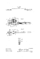
- FIG. 1 is a side elevation of a pipe wrench embodying the'improvements set forth.
- FIG. 2 is a transverse sectional detail of the same taken on the line AA of Fig. 1.
- Fig. 3 is a similar view taken. on the line BB of Fig. 1.
- Fig. 4- is a perspective view of one of the jaws.
- Fig. 5 is a plan view of the lever.
- Fig. 5 is a side elevation of a pipe cutter embodying the improvements set forth.
- Fig. 7 is a bottom plan view of the same.
- Fig. 8 is a-transverse sectional detail taken on the line CG-of Fig. 6.
- the body member or housing 1 is formed preferably of sheet metal bent substantially U-shaped and secured together at the ends thereof by means of a transverse plate 2 and secured intermediate of its ends by means of the transverse plates 3.
- the member has a. recess 4 within which is located the rotatable member or adjusting nut 5.
- An operating arm or lever (3 has-its inner end located within the U-shaped member and pivotally minnectedthereto by means oi a pin 7.
- a bar 8 is shiitabiy mounted within the U-shapod member 1 on the opposite side of the. plates 3 from the lever (3.
- the upper and lower edges of bar 8 are pro vidod with throadsl) which are engaged by the threaded member or nut 5 whereby Specification of Letters Patent.
- the tool is provided with gripping members which are adapted to be forced together to engage the work.
- the form of these members will of course vary in diiierent kinds of tools.
- these members are in the form of serrated jaws.
- the jaw 10 is integrally formed on the transverse part 8.1 of the-bar 8 and opposed to the jaw 11 which is pivotally connected to the supporting member 1 by means of the pin 19..
- the jaw 11 is formed of two L-shaped parts which are connected together by means of a rivet 13 as shown in Fig. 4.
- the gripping members would be in the shape of a rotary cutter rotatably supported on the jaw 11, and rollers 24 journaled in the transverse part 8.1 of the bar 8.
- the lever 6 is shaped to interfit with the nut 5 so that the power is applied to the nut directly.
- the lever has a radially disposed rib or lug 11 of the width of the lever 6 and which eX- tends into an annular groove 15 formed in the rotatable member or nut 5.
- the tongue 14. has its end formed concave to fit the contour of the groove in the nut 5.
- a groove or slot 15.1 is formed in the lever G and an annular shoulder or tongue 14.1 is formed on the nut 5. This connection between the lever 6 and rotatable member 5 causes the bar 8 to be shifted.
- a cam 16 is formed on the lever 6 and adapted to bear upon the adjacent face 17 of the jaw 11 so that when the lever is swung to shift the bar 8 rearwardly the outer end of the jaw 12 is tilted toward the jaw 10.
- A. spring 18- is located in a recess 19 formed in the lover 6 and bears against the adjacent plate 3 so as to normally shift the lever for urging the gripping members t ward each other so that in placing the wrench upon the work they will, if necessary yield slightly.
- a device of the class described comprising a body member, a lever pivotally mounted on said member, jaws mounted on said member separately” from said lever and being relatively movable in substantial alinement therewith, means connecting said being relatively movable in substantial alinement therewith, means connecting said lever with one of said jaws whereby said jaw is shifted longitudinally of said lever by a swinging movement thereof, the same comprising a transverse rib on 'said lever, a
Description
c. A. DIES WRENCH.
APPLICATON LED FEB- 9,1914- RENEWED MAR. 5.1915- l,155.,136. PatentedSept. 28, 1915.
2 SHEETS-SHEET I.
C. A. DiES.
WRENCH.
APPLICATION FILED FEB-9,1914. RENEWED MAR. 5,1915.
Patented Sept. 28, 1915.
2 SHEETS-SHEET 2.
//2 rep for.
W/ff ess es. I w
M NA CHARLES ALBIN DIES, OF CHICAGO, ILLINOIS.
WRENCH.
Application filed February 9, 1914, Serial No. 817,549. Renewed March 5, 1915.
To all whom it may concern:
Be it known that I, CHARLES ALBIN DIES, a citizen of the United States of America, and a resident of Chicago, county of Cook, and State of Illinois, new and useful Improvements in Vrenches, of which the following is a specification.
This invention relates to that type of pipe and other wrenches in which a manual pull on the handle forces a'pivoted jaw member to the work. And the present improvement has for its object to provide a simple and eliicient structural formation and arrangement of parts, whereby a sliding movement of one jaw and, a pivotal movement of a companion jaw of the wrench are simultaneously effected by a pull on the wrench 'handlepand with an absence of a thrust stress uponthe intermediate housing which carries the jaws aforesaid all as Wlll 'horenr after more fully appear.
An illustrative embodiment of this invention 13 shown in the accompanying drawings, in which- Figure l is a side elevation of a pipe wrench embodying the'improvements set forth. Fig. 2 is a transverse sectional detail of the same taken on the line AA of Fig. 1. Fig. 3 is a similar view taken. on the line BB of Fig. 1. Fig. 4- is a perspective view of one of the jaws. Fig. 5 is a plan view of the lever. Fig. 5 is a side elevation of a pipe cutter embodying the improvements set forth. Fig. 7 is a bottom plan view of the same. Fig. 8 is a-transverse sectional detail taken on the line CG-of Fig. 6.
In theconstruction shown in the drawings,-the body member or housing 1 is formed preferably of sheet metal bent substantially U-shaped and secured together at the ends thereof by means of a transverse plate 2 and secured intermediate of its ends by means of the transverse plates 3. The member has a. recess 4 within which is located the rotatable member or adjusting nut 5.
An operating arm or lever (3 has-its inner end located within the U-shaped member and pivotally minnectedthereto by means oi a pin 7. A bar 8 is shiitabiy mounted within the U-shapod member 1 on the opposite side of the. plates 3 from the lever (3. The upper and lower edges of bar 8 are pro vidod with throadsl) which are engaged by the threaded member or nut 5 whereby Specification of Letters Patent.
have invented certain Patented Sept. as, 1915.
Serial No. 12,409.
the rotation of said member will cause said bar to be moved along the lever 6.
The tool is provided with gripping members which are adapted to be forced together to engage the work. The form of these members will of course vary in diiierent kinds of tools. In the pipe wrench illustrated in the drawings these members are in the form of serrated jaws. The jaw 10 is integrally formed on the transverse part 8.1 of the-bar 8 and opposed to the jaw 11 which is pivotally connected to the supporting member 1 by means of the pin 19.. The jaw 11 is formed of two L-shaped parts which are connected together by means of a rivet 13 as shown in Fig. 4. In another tool such as the pipe cutter shown herein the gripping members would be in the shape of a rotary cutter rotatably supported on the jaw 11, and rollers 24 journaled in the transverse part 8.1 of the bar 8.
The lever 6 is shaped to interfit with the nut 5 so that the power is applied to the nut directly. As shown on the pipe wrench the lever has a radially disposed rib or lug 11 of the width of the lever 6 and which eX- tends into an annular groove 15 formed in the rotatable member or nut 5. The tongue 14. has its end formed concave to fit the contour of the groove in the nut 5. As shown on the pipe cutter a groove or slot 15.1 is formed in the lever G and an annular shoulder or tongue 14.1 is formed on the nut 5. This connection between the lever 6 and rotatable member 5 causes the bar 8 to be shifted. a short distance, through a swinging movement of the lever 6 and after the gripping members have been pro )erly adjusted by means of the adjusting ut 5, so that as they arei'orced to grip the work the strain on the bar .8 is directed through the tongue and groove to the lever 6.
A cam 16 is formed on the lever 6 and adapted to bear upon the adjacent face 17 of the jaw 11 so that when the lever is swung to shift the bar 8 rearwardly the outer end of the jaw 12 is tilted toward the jaw 10.
A. spring 18- is located in a recess 19 formed in the lover 6 and bears against the adjacent plate 3 so as to normally shift the lever for urging the gripping members t ward each other so that in placing the wrench upon the work they will, if necessary yield slightly.
. As shown in Fig. 5 the lever 6 is enlarged" at 22 in the vicinity of the recess 19 and the fulcrum pin.
The operation of the device shown is as follows: When it is desired to use the wrench the rotatable member 5 is turned until the jaws 10 and 11 both engage the work.' A pull upon the lever 6 causes the tongue 14, which acts upon the rotatable member 5, to urge the bar 8 rearwardly, and causes the cam 16 to shift the outer end of the jaw 11 toward the jaw 10. By virtue of the connection of the lever 6 to the rotary member 5 and its connection to the bar 8, the strain on the aw 10 is directed to the lever 6 thereby relieving the body member 1 from the thrust and strain which usually occurs in other wrenches of this general type. The pipe cutter is used in a similar manner as is obvious.
By reason of the fact that there is no tilting of the bar 8 as in other Wrenches of this general type, it is possible to use the wrench for backing-0E a nut without the likelihood of its slipping iree from the nut due to enlargement of the distance between the jaws 10 and 11. The play of the nut 5 in the recess 4: need only be enough to allow the jaws 10 and 11 to move a sufficient distance to cause the teeth 'to alternately grip and release a pipe as the lever 6 is rocked forward and back in the well-known manner as the pipe is turned.
Although but one specific embodiment of this invention has been herein shown and described, it will be understood that some of the details of the construction shown may be altered or omitted without departing from the spirit of this invention as defined by the following claims. I claim: 1., A device of the class described, comprising a body member, a lever pivotally mounted on said member, jaws mounted on said member separately" from said lever and being relatively movable in substantial alinement therewith, means connecting said being relatively movable in substantial alinement therewith, means connecting said lever with one of said jaws whereby said jaw is shifted longitudinally of said lever by a swinging movement thereof, the same comprising a transverse rib on 'said lever, a
sleeve nut operatively associated with said rib and adjustably connected to said jaw by and a cam car-- ried by said lever and adapted to shift the a screw-thread connection,
other jaw when said lever is swung and thereby force said jaws together. a
Signed at Chicago this 7th d y of February, 1914. j
CHARLES ALBIN DIES.
Witnesses:
Ronow RUMMLER, M. IRENE HU'roHINGs.
Priority Applications (1)
| Application Number | Priority Date | Filing Date | Title |
|---|---|---|---|
| US1240915A US1155136A (en) | 1915-03-05 | 1915-03-05 | Wrench. |
Applications Claiming Priority (1)
| Application Number | Priority Date | Filing Date | Title |
|---|---|---|---|
| US1240915A US1155136A (en) | 1915-03-05 | 1915-03-05 | Wrench. |
Publications (1)
| Publication Number | Publication Date |
|---|---|
| US1155136A true US1155136A (en) | 1915-09-28 |
Family
ID=3223198
Family Applications (1)
| Application Number | Title | Priority Date | Filing Date |
|---|---|---|---|
| US1240915A Expired - Lifetime US1155136A (en) | 1915-03-05 | 1915-03-05 | Wrench. |
Country Status (1)
| Country | Link |
|---|---|
| US (1) | US1155136A (en) |
Cited By (3)
| Publication number | Priority date | Publication date | Assignee | Title |
|---|---|---|---|---|
| US2567432A (en) * | 1946-02-12 | 1951-09-11 | Dozier F Hasty | Nut-fulcrumed pivoted jaw wrench |
| US2567833A (en) * | 1948-09-04 | 1951-09-11 | Chester E Warren | Pipe cutter |
| US2741743A (en) * | 1951-09-14 | 1956-04-10 | Edward A Kern | Indicating instrument |
-
1915
- 1915-03-05 US US1240915A patent/US1155136A/en not_active Expired - Lifetime
Cited By (3)
| Publication number | Priority date | Publication date | Assignee | Title |
|---|---|---|---|---|
| US2567432A (en) * | 1946-02-12 | 1951-09-11 | Dozier F Hasty | Nut-fulcrumed pivoted jaw wrench |
| US2567833A (en) * | 1948-09-04 | 1951-09-11 | Chester E Warren | Pipe cutter |
| US2741743A (en) * | 1951-09-14 | 1956-04-10 | Edward A Kern | Indicating instrument |
Similar Documents
| Publication | Publication Date | Title |
|---|---|---|
| US1086078A (en) | Plier-wrench. | |
| US1155136A (en) | Wrench. | |
| US701237A (en) | Pipe-wrench. | |
| US430994A (en) | Pipe-wrench | |
| US1520613A (en) | Pliers | |
| US1143350A (en) | Pipe-wrench. | |
| US1115439A (en) | Pipe-wrench. | |
| US714364A (en) | Automatic grip-wrench. | |
| US278264A (en) | Pipe-tongs | |
| US1060391A (en) | Wrench. | |
| US483334A (en) | sperrt | |
| US877225A (en) | Pipe-wrench. | |
| US410384A (en) | Charles a | |
| US766458A (en) | Pipe-wrench. | |
| US1019280A (en) | Pipe-wrench. | |
| US1302009A (en) | Pipe and nut wrench. | |
| US1194271A (en) | And carl w | |
| US1027452A (en) | Wrench. | |
| US419854A (en) | Pipe-wrench | |
| US1093253A (en) | Wrench. | |
| US1138728A (en) | Automatic adjusting pipe-wrench. | |
| US743227A (en) | Wrench. | |
| US405343A (en) | Combined nut and pipe wrench | |
| US765007A (en) | Pipe-wrench. | |
| US1269188A (en) | Wrench. |