EP2476512A1 - Bandabblasvorrichtung - Google Patents
Bandabblasvorrichtung Download PDFInfo
- Publication number
- EP2476512A1 EP2476512A1 EP12151364A EP12151364A EP2476512A1 EP 2476512 A1 EP2476512 A1 EP 2476512A1 EP 12151364 A EP12151364 A EP 12151364A EP 12151364 A EP12151364 A EP 12151364A EP 2476512 A1 EP2476512 A1 EP 2476512A1
- Authority
- EP
- European Patent Office
- Prior art keywords
- nozzles
- nozzle
- rows
- grinding
- belt
- Prior art date
- Legal status (The legal status is an assumption and is not a legal conclusion. Google has not performed a legal analysis and makes no representation as to the accuracy of the status listed.)
- Granted
Links
Images

Classifications
-
- B—PERFORMING OPERATIONS; TRANSPORTING
- B24—GRINDING; POLISHING
- B24B—MACHINES, DEVICES, OR PROCESSES FOR GRINDING OR POLISHING; DRESSING OR CONDITIONING OF ABRADING SURFACES; FEEDING OF GRINDING, POLISHING, OR LAPPING AGENTS
- B24B21/00—Machines or devices using grinding or polishing belts; Accessories therefor
- B24B21/18—Accessories
-
- B—PERFORMING OPERATIONS; TRANSPORTING
- B24—GRINDING; POLISHING
- B24B—MACHINES, DEVICES, OR PROCESSES FOR GRINDING OR POLISHING; DRESSING OR CONDITIONING OF ABRADING SURFACES; FEEDING OF GRINDING, POLISHING, OR LAPPING AGENTS
- B24B55/00—Safety devices for grinding or polishing machines; Accessories fitted to grinding or polishing machines for keeping tools or parts of the machine in good working condition
- B24B55/06—Dust extraction equipment on grinding or polishing machines
- B24B55/08—Dust extraction equipment on grinding or polishing machines specially designed for belt grinding machines
Definitions
- the invention relates to a Bandabblasvorraum for a grinding belt in a processing machine, which is intended for the machining of workpieces, which are preferably made of wood, wood-like materials and / or metal.
- blowing devices are individually controllable, so that each for a blowing device or a group of blowing devices, a control valve and a sensor is provided which detects the contour of the workpiece to be machined and provides information to a control unit, according to the contour of the individual blowing devices or a Group of adjacent blowing devices drives.
- the present invention is based on the problem that the cleaning effect of some of the conventional blow-off devices are indeed sufficient for the cleaning of a workpiece, since there are usually smooth surfaces, but provide only insufficient performance for the cleaning of an abrasive belt. Although other conventional blow-off devices can adequately clean an abrasive belt, these devices have very high mechanical wear due to the high operating frequency.
- the individual rows of nozzles are preferably operated sequentially one after the other. As a result, the cleaning result of the abrasive belt is further improved.
- the nozzle assembly is preferably made in a continuous casting of aluminum or plastic, so that the lines and interfaces more preferably all can be configured integrally with the nozzles.
- the nozzle arrangement preferably the Entire Bandabblasvoriques, movably arranged. This movement again preferably takes place in a plane parallel to the running direction of the grinding belt, more preferably in a direction parallel or perpendicular to the running direction. The movement is preferably carried out at a frequency of 0.1 Hz to 1.5 Hz, but preferably at 0.5 Hz. This further increases the cleaning effect, in particular together with a sequential control of the nozzle rows.
- the nozzles of the individual rows of nozzles are each offset so that the staggered nozzle rows are substantially on a straight line connecting. That is, the offset distance of each row of nozzles to the next row of nozzles is always constant, preferably about 30 mm. Again, an improved cleaning effect is achieved by the arrangement of the obliquely offset rows of nozzles.
- the nozzles of one or more nozzle rows are preferably inclined obliquely to the grinding belt, in particular to the side.
- a grinding unit or the belt blow-off device is preferably used in a processing machine, which also has a conveyor for workpieces.
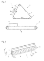
- FIG. 1 is a processing machine to see a conveyor 5 with a conveyor belt 6, on which a workpiece 4 is located, a rotating grinding unit 2 with and a Bandabblasvorraum 1.
- the workpiece 4 is transported by conveyor 5 on the conveyor belt 6 to the grinding unit 2 and processed there by this grinding belt 3.
- the revolving grinding unit 2 in the present embodiment is a grinding belt 3, since this is a commonly used grinding unit 2.
- Other moving grinding units are included in the invention.
- the grinding dust produced during grinding then settles both on the workpiece 4 and on the grinding belt 3.
- this belt blowing device is in principle suitable for being used also for the cleaning of workpieces. In such a case, the design of the Bandabblasvoroplasty relative to the grinding unit, the funded workpiece to bezieher.
- the tape blowing apparatus 1 has a nozzle assembly 8 and a control device (not shown).
- a Bandabblasvorraum 1 can be seen, which includes three nozzle rows 10.
- a nozzle row 10 consists of a continuous casting profile with a plurality of individual nozzles.
- the term "nozzles" in the simplest form also includes mere holes or holes in the continuous casting profile through which the air is expelled.
- the nozzles are additional elements designed specifically for directional ejection of the air.
- Such nozzles are exemplary in the FIGS. 5 and 6 to recognize.
- special nozzles are threaded into a continuous casting profile containing compressed air lines connecting the nozzles 12 together.
- the nozzles 12 are screwed into receptacles 9 provided for this purpose.
- the individual nozzles 12 need not be screwed into a continuous casting profile, they can also be connected with a simple plug connection, welded or be formed integrally with the continuous casting profile.
- the continuous cast profile itself is again preferably made of aluminum, a steel or a plastic.
- the individual rows of nozzles 10 may each be designed as individual continuous casting profiles, or may be formed in one piece, so that two or more rows of nozzles are formed in a single continuous casting profile.
- the individual rows of nozzles 10 can preferably be stackable in a modular manner, so that further rows of nozzles 10 can be easily attached to the existing nozzle arrangement 8.
- a nozzle arrangement 8 comprises at least two rows of nozzles 10, but preferably three, four or even more, which are arranged one above the other, ie offset in the z-direction. More preferably, the rows of nozzles 10 are offset in the x-direction to each other by a distance v, the ideally 25th mm to 35 mm, more preferably 30 mm.
- the distance v is preferably constant, so that the individual nozzle rows 10 are offset from one another by the same distance and the corresponding nozzles 12 of the different groups G1 G2, G3 lie on a straight line.
- the nozzle arrangement 8 has one or more interfaces 11 via which compressed air is introduced from an external compressed air line or a compressed air suction device (not shown).
- the compressed air introduction is preferably determined by a solenoid valve unit which controls the air supply in the various compressed air lines by opening and closing the corresponding valves.
- compressed air is the preferred fluid for use with the present invention
- various fluids or gases best suited to the particular purpose and environment may be used.
- humid air may also be used which, for example, may additionally have a humidity of from 20% to 80%, allowing the blown-off dust to bind in the moisture and therefore be easier to remove.
- the nozzle assembly 8 is arranged so that it is directed to the sanding belt 3, more specifically, that the nozzles 12 of the nozzle rows 10 are directed to the sanding belt 3, ie the ejected air can hit the sanding belt 3.
- FIG. 5 An embodiment is shown in which the orientation of the nozzles 12 is formed perpendicular to the abrasive belt 3. However, an orientation is preferred in which the nozzles 12 are aligned obliquely to the grinding belt 3 (see FIG. 6 ).
- Slanting may theoretically mean in any direction, for example, in one direction in or against the direction of travel of the abrasive belt 3 during operation, which corresponds to alignment in a yz plane, but is preferably oriented in the xy plane, as in FIG FIG. 6 is shown.
- the inclination of the nozzles 12 is preferably in a range of about 25 ° to 55 ° to the side, preferably 30 ° to 40 ° and more preferably about 35 ° to a straight orientation, as in FIG. 5 you can see.
- the nozzles 12 may be inclined in the same direction both in the x-direction and in the y-direction.
- the inclination of the nozzles 12 is preferably made to be alternate, so that the individual nozzle groups G1, G2, G3 are inclined in opposite directions.
- the nozzle assembly 8 or the entire Bandabblasvorraum 1 is further preferably also mounted linearly movable.
- the movement is preferably in a plane E, which extends parallel to the grinding belt 3, in a preferred embodiment, the movement is transverse or parallel to Running direction L in the plane E.
- the movement takes place in a frequency of 0.1 Hz to 1.5 Hz, preferably at 0.5 Hz.
- the movement is generated, for example, by an oscillating cylinder (not shown), which controls the nozzle arrangement or even only the nozzle rows (the Continuous casting profile) can move and is stored even outside the arrangement, or outside the nozzle rows.
- this oscillating cylinder has a coupling which is arranged between the cylinder and the respective moving element and can compensate for mechanical stresses.
- the control of the individual nozzle rows 10 or the individual nozzles 12 is generally independent of each other.
- a valve on the Interface can be provided which can cut off the supply of compressed air into the pressure lines of the nozzle rows 10, so that the nozzles 12 of the corresponding row of nozzles 10 do not expel air.
- each individual nozzle is provided with a valve, but preferably the line of the entire row of nozzles 10 is provided with only one valve and so all the nozzles 12 of a row of nozzles 10 are controlled simultaneously.
- stop valves which can be provided in the pressure lines, so that only a part of a row of nozzles 10 from a respective group can blow out air (eg only the left half or the left third).
- nozzle assembly 8 it can also be provided on both sides of the nozzle assembly 8, an interface for the supply of compressed air, so that both sides can be controlled and the left or right half each individually blow air.
- this approach is not on “halves.” limited, but the stop valves, the nozzle rows each divide into thirds or quarters. In the extreme case, each nozzle can be controlled individually.
- a fairly simple realization of a stop valve could be single blind plugs inserted into a nozzle hole instead of a nozzle can be used and then block the compressed air line, so that the air flow is interrupted.
- blind plugs can be made, for example, of rubber and in a form which is adapted to the respective pressure line.
- a web can be provided around the nozzles and / or between the nozzles or the nozzle rows Surface of the nozzle assembly on which the nozzles are arranged, lifts, so that the nozzles are protected.
- this web between the nozzle rows protrude vertically, so that an oblique orientation of the nozzle as in FIG. 6 can blow out the air without being obstructed by the bridge.
- the web is preferably slightly higher than the nozzles protrude.
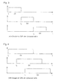
- FIGS. 3 and 4 show preferred activations of the nozzle rows 10.
- the individual nozzle groups have a preset actuation time t1, t2, t3 within one cycle.
- One cycle describes the activation of the groups G1, G2, G3, which repeats itself again and again.
- the drive timing marks the beginning of the ejection of air from the nozzles of the corresponding group.
- the duration for which the respective group is activated, ie air inflates, can be adjusted.
- Examples of a nozzle arrangement are shown which shows three groups whose activation time, that is to say the time duration for which a group blows out air, is preferably distributed uniformly over one cycle.
- nozzles are also preferably driven uniformly over one cycle. Basically, one can say that in the preferred embodiment, one cycle with the drive time of the first driven group (here G1 begins, and ends with the switching off of the last controlled group (here G3).
- the control for the in FIG. 3 shown embodiment described with three rows of nozzles.
- the solenoid valve of group 1 is driven for a certain time, preferably one turn of the belt 3 (for example 1 sec at a belt revolution of 2 m / sec and a belt length of 2 m), and blown out air from group 1.
- group 2 is switched on for the same time.
- group 3 is switched on for the same time.
- group 3 is activated and the process repeated.
- the procedure is analogous, with the first group being switched on again when the last group is switched off.
- the subsequent group could not be activated directly after the preceding group was switched off, but simultaneously with the shutdown.
- the operation of the individual groups can also overlap.
- the control can generally be done in any order. For 3 groups, this may only lead to a reversal of the control, but in four groups the order can also be G1-G3-G2-G4 or G1-G2-G4-G3.
- the activation of different groups can also take place simultaneously. For example, if there are six rows of nozzles 10, group 1 and group 4 would blow out simultaneously for the six groups, group 2 and group 5, and group 3 and group 6.
- the length of the control can be adjusted via an operating terminal.
- a cycle whose duration can be set separately and preferably as a function of the grinding belt length and / or the grinding belt speed is assumed to be 100% or 1.
- the length of the nozzle operation of the individual groups G1, G2, G3 is set to 33.3% and 1/3, respectively.
- group 2 switches on simultaneously with the disconnection of group 1.
- an overlap of the control of the individual group can be set, so that, for example, group 1 is switched off only after half of the Zeitimoulses of group 2, while simultaneously or directly after group 3 is switched on.
- FIG. 4 is an example of a setting of 66%, or 2/3 shown.
- This overlap can be adjusted until all nozzle rows 10 run at 100%, or 1 at the same time. As a result, the maximum cleaning effect is deployed. With three groups and an operating time of a group of less than 33.3%, or 1/3, there is a short break between the groups. However, this can already be sufficient for a light cleaning of, for example, very smooth surfaces and thus further reduce the air consumption. In an exemplary embodiment, there are 5 stages to which the drive time of 20%, 33%, 50%, 66% and 100% are incrementally assigned from 1 to 5. A stepless adjustment is also possible.
- the time period that a group is driven is also set as a function of the grinding belt speed. As a result, a shorter pulse length for the individual groups could be sufficient given an increasing grinding belt speed.
- the nozzle assembly 8 itself may also be designed to be movable, as already mentioned above.
- an oscillation of the nozzle assembly 8 can be much lower than in the prior art.
- a suction device 13 is provided around the nozzle assembly 8, which can absorb and carry away the dust which is blown by the abrasive belt 3.
Applications Claiming Priority (1)
| Application Number | Priority Date | Filing Date | Title |
|---|---|---|---|
| DE201110002808 DE102011002808A1 (de) | 2011-01-18 | 2011-01-18 | Bandabblasvorrichtung |
Publications (2)
| Publication Number | Publication Date |
|---|---|
| EP2476512A1 true EP2476512A1 (de) | 2012-07-18 |
| EP2476512B1 EP2476512B1 (de) | 2014-04-30 |
Family
ID=45554486
Family Applications (1)
| Application Number | Title | Priority Date | Filing Date |
|---|---|---|---|
| EP20120151364 Not-in-force EP2476512B1 (de) | 2011-01-18 | 2012-01-17 | Bandabblasvorrichtung |
Country Status (2)
| Country | Link |
|---|---|
| EP (1) | EP2476512B1 (ar) |
| DE (1) | DE102011002808A1 (ar) |
Cited By (4)
| Publication number | Priority date | Publication date | Assignee | Title |
|---|---|---|---|---|
| CN105397598A (zh) * | 2015-12-07 | 2016-03-16 | 重庆艾布特家具有限公司 | 新型磨平设备 |
| EP3006162A1 (de) * | 2014-10-09 | 2016-04-13 | Georg Weber | Vorrichtung zum ausblasen eines umlaufenden schleifbands einer bandschleifmaschine |
| CN109333266A (zh) * | 2018-10-28 | 2019-02-15 | 昆山锲恒精密组件科技有限公司 | 一种镁铝合金研磨装置及研磨工艺 |
| CN117399225A (zh) * | 2023-12-13 | 2024-01-16 | 沧州融通管道装备有限公司 | 一种节能型保温管道防腐加工设备 |
Families Citing this family (4)
| Publication number | Priority date | Publication date | Assignee | Title |
|---|---|---|---|---|
| DE102016209267A1 (de) | 2016-05-30 | 2017-11-30 | Schaeffler Technologies AG & Co. KG | Gehäuse |
| DE102016209519A1 (de) | 2016-06-01 | 2017-12-07 | Schaeffler Technologies AG & Co. KG | Steckverbindung |
| DE102017117715A1 (de) * | 2017-08-04 | 2019-02-07 | Homag Gmbh | Absaugungsvorrichtung mit optimierter Staubabsaugung |
| DE102020112995A1 (de) | 2020-05-13 | 2021-11-18 | Haver & Boecker Ohg | Reinigungsvorrichtung und Verfahren zum Reinigen |
Citations (3)
| Publication number | Priority date | Publication date | Assignee | Title |
|---|---|---|---|---|
| CH405975A (de) | 1964-01-23 | 1966-01-15 | Rusterholz Erich | Vorrichtung zum Abblasen des Schleifstaubes von Schleifkörpern, insbesondere Schleifbändern |
| DE4232830C1 (de) | 1992-09-30 | 1993-10-21 | Georg Weber | Vorrichtung zum Entfernen von Schleifstaub von Werkstücken in Schleifmaschinen |
| EP0724933A1 (de) | 1995-01-11 | 1996-08-07 | Jürgen Dipl.-Ing. Heesemann | Abstrahlvorrichtung für eine Bandschleifmaschine |
Family Cites Families (3)
| Publication number | Priority date | Publication date | Assignee | Title |
|---|---|---|---|---|
| JPS57201171A (en) * | 1981-06-02 | 1982-12-09 | Meinan Mach Works Inc | Polishing device |
| US5616069A (en) * | 1995-12-19 | 1997-04-01 | Micron Technology, Inc. | Directional spray pad scrubber |
| US6669538B2 (en) * | 2000-02-24 | 2003-12-30 | Applied Materials Inc | Pad cleaning for a CMP system |
-
2011
- 2011-01-18 DE DE201110002808 patent/DE102011002808A1/de not_active Withdrawn
-
2012
- 2012-01-17 EP EP20120151364 patent/EP2476512B1/de not_active Not-in-force
Patent Citations (3)
| Publication number | Priority date | Publication date | Assignee | Title |
|---|---|---|---|---|
| CH405975A (de) | 1964-01-23 | 1966-01-15 | Rusterholz Erich | Vorrichtung zum Abblasen des Schleifstaubes von Schleifkörpern, insbesondere Schleifbändern |
| DE4232830C1 (de) | 1992-09-30 | 1993-10-21 | Georg Weber | Vorrichtung zum Entfernen von Schleifstaub von Werkstücken in Schleifmaschinen |
| EP0724933A1 (de) | 1995-01-11 | 1996-08-07 | Jürgen Dipl.-Ing. Heesemann | Abstrahlvorrichtung für eine Bandschleifmaschine |
Cited By (5)
| Publication number | Priority date | Publication date | Assignee | Title |
|---|---|---|---|---|
| EP3006162A1 (de) * | 2014-10-09 | 2016-04-13 | Georg Weber | Vorrichtung zum ausblasen eines umlaufenden schleifbands einer bandschleifmaschine |
| CN105397598A (zh) * | 2015-12-07 | 2016-03-16 | 重庆艾布特家具有限公司 | 新型磨平设备 |
| CN109333266A (zh) * | 2018-10-28 | 2019-02-15 | 昆山锲恒精密组件科技有限公司 | 一种镁铝合金研磨装置及研磨工艺 |
| CN117399225A (zh) * | 2023-12-13 | 2024-01-16 | 沧州融通管道装备有限公司 | 一种节能型保温管道防腐加工设备 |
| CN117399225B (zh) * | 2023-12-13 | 2024-02-09 | 沧州融通管道装备有限公司 | 一种节能型保温管道防腐加工设备 |
Also Published As
| Publication number | Publication date |
|---|---|
| DE102011002808A1 (de) | 2012-07-19 |
| EP2476512B1 (de) | 2014-04-30 |
Similar Documents
| Publication | Publication Date | Title |
|---|---|---|
| EP2476512B1 (de) | Bandabblasvorrichtung | |
| EP2283908B1 (de) | Vorrichtung zur Aufbereitung von Kühlschmierstoff | |
| EP3229935B1 (de) | Luftreinigungsanlage | |
| EP3357592A1 (de) | Reinigungsstation | |
| EP1918458B1 (de) | Vorrichtung zum Schleifen eines Profils mittels eines umlaufenden Schleifbands | |
| EP3006162A1 (de) | Vorrichtung zum ausblasen eines umlaufenden schleifbands einer bandschleifmaschine | |
| EP1700643A2 (de) | Behälteraufgabe | |
| EP1900449B1 (de) | Spritzbalken einer hydraulischen Entzunderungsanlage und Verfahren zum Betreiben eines solchen Spritzbalkens | |
| EP0603647B1 (de) | Vorrichtung zum kontinuierlichen Herstellen von Schaumstoffbahnen, insbesondere Hartschaumstoffplatten | |
| EP0522093A1 (de) | Verfahren und vorrichtung zum reinigen eines umlaufenden papiermaschinensiebes | |
| DE102007047554B3 (de) | Verfahren zur Reinigung der Aperturen von Druckmasken sowie Düsenkopf zur Durchführung dieses Verfahrens | |
| EP0979985B1 (de) | Vorrichtung zur Wärmebehandlung einer textilen Warenbahn | |
| EP1509342B1 (de) | Trockenreinigungsanlage für werkstücke | |
| EP1123747A2 (de) | Pulverbeschichtungsanlage | |
| DE102016108256A1 (de) | Nachrüstungsset, Lauffähigkeitskomponente und Verfahren zum Modifizieren eines Saugkastens | |
| DE102009032907B3 (de) | Vorrichtung zum Entfernen von Rückständen von der Oberfläche eines bewegten Bandes sowie Bandbearbeitungsanlage | |
| EP0391091B1 (de) | Unterdruck-Bandfilter-Anlage | |
| EP0511515B1 (de) | Flockierwalzwerk | |
| DE3910930C2 (ar) | ||
| EP3976334B1 (de) | Vorrichtung und verfahren zur herstellung eines vlieses | |
| DE4235651C2 (de) | Verfahren zum Durchlauf-Vakuumbeschichten sowie Durchlauf-Vakuumbeschichtungskammer | |
| EP2644342B1 (de) | Verfahren sowie Vorrichtung zur Bearbeitung von Formsteinen aus zementgebundenem Material, beispielsweise Beton | |
| DE102007055584C5 (de) | Reinigungseinrichtung und Verfahren zum Reinigen von Filtern | |
| DE3929490A1 (de) | Verfahren und vorrichtung zum taktweisen abheben eines an einer bewegbar gelagerten putzleiste angeordneten abstreifelements | |
| EP1464754A2 (de) | Vorrichtung zum Reinigen eines umlaufenden Bandes |
Legal Events
| Date | Code | Title | Description |
|---|---|---|---|
| PUAI | Public reference made under article 153(3) epc to a published international application that has entered the european phase |
Free format text: ORIGINAL CODE: 0009012 |
|
| AK | Designated contracting states |
Kind code of ref document: A1 Designated state(s): AL AT BE BG CH CY CZ DE DK EE ES FI FR GB GR HR HU IE IS IT LI LT LU LV MC MK MT NL NO PL PT RO RS SE SI SK SM TR |
|
| AX | Request for extension of the european patent |
Extension state: BA ME |
|
| GRAP | Despatch of communication of intention to grant a patent |
Free format text: ORIGINAL CODE: EPIDOSNIGR1 |
|
| 17P | Request for examination filed |
Effective date: 20130116 |
|
| RIC1 | Information provided on ipc code assigned before grant |
Ipc: B24B 55/00 20060101ALI20130206BHEP Ipc: B24B 55/08 20060101ALI20130206BHEP Ipc: B24B 21/18 20060101AFI20130206BHEP |
|
| GRAS | Grant fee paid |
Free format text: ORIGINAL CODE: EPIDOSNIGR3 |
|
| 17Q | First examination report despatched |
Effective date: 20130705 |
|
| RAP1 | Party data changed (applicant data changed or rights of an application transferred) |
Owner name: WEEKE BOHRSYSTEME GMBH |
|
| GRAP | Despatch of communication of intention to grant a patent |
Free format text: ORIGINAL CODE: EPIDOSNIGR1 |
|
| INTG | Intention to grant announced |
Effective date: 20131204 |
|
| GRAA | (expected) grant |
Free format text: ORIGINAL CODE: 0009210 |
|
| AK | Designated contracting states |
Kind code of ref document: B1 Designated state(s): AL AT BE BG CH CY CZ DE DK EE ES FI FR GB GR HR HU IE IS IT LI LT LU LV MC MK MT NL NO PL PT RO RS SE SI SK SM TR |
|
| REG | Reference to a national code |
Ref country code: GB Ref legal event code: FG4D Free format text: NOT ENGLISH Ref country code: CH Ref legal event code: EP |
|
| REG | Reference to a national code |
Ref country code: AT Ref legal event code: REF Ref document number: 664771 Country of ref document: AT Kind code of ref document: T Effective date: 20140515 |
|
| REG | Reference to a national code |
Ref country code: IE Ref legal event code: FG4D Free format text: LANGUAGE OF EP DOCUMENT: GERMAN |
|
| REG | Reference to a national code |
Ref country code: DE Ref legal event code: R096 Ref document number: 502012000636 Country of ref document: DE Effective date: 20140612 |
|
| REG | Reference to a national code |
Ref country code: LT Ref legal event code: MG4D |
|
| REG | Reference to a national code |
Ref country code: NL Ref legal event code: VDEP Effective date: 20140430 |
|
| PG25 | Lapsed in a contracting state [announced via postgrant information from national office to epo] |
Ref country code: NO Free format text: LAPSE BECAUSE OF FAILURE TO SUBMIT A TRANSLATION OF THE DESCRIPTION OR TO PAY THE FEE WITHIN THE PRESCRIBED TIME-LIMIT Effective date: 20140730 Ref country code: CY Free format text: LAPSE BECAUSE OF FAILURE TO SUBMIT A TRANSLATION OF THE DESCRIPTION OR TO PAY THE FEE WITHIN THE PRESCRIBED TIME-LIMIT Effective date: 20140430 Ref country code: GR Free format text: LAPSE BECAUSE OF FAILURE TO SUBMIT A TRANSLATION OF THE DESCRIPTION OR TO PAY THE FEE WITHIN THE PRESCRIBED TIME-LIMIT Effective date: 20140731 Ref country code: BG Free format text: LAPSE BECAUSE OF FAILURE TO SUBMIT A TRANSLATION OF THE DESCRIPTION OR TO PAY THE FEE WITHIN THE PRESCRIBED TIME-LIMIT Effective date: 20140730 Ref country code: NL Free format text: LAPSE BECAUSE OF FAILURE TO SUBMIT A TRANSLATION OF THE DESCRIPTION OR TO PAY THE FEE WITHIN THE PRESCRIBED TIME-LIMIT Effective date: 20140430 Ref country code: FI Free format text: LAPSE BECAUSE OF FAILURE TO SUBMIT A TRANSLATION OF THE DESCRIPTION OR TO PAY THE FEE WITHIN THE PRESCRIBED TIME-LIMIT Effective date: 20140430 Ref country code: LT Free format text: LAPSE BECAUSE OF FAILURE TO SUBMIT A TRANSLATION OF THE DESCRIPTION OR TO PAY THE FEE WITHIN THE PRESCRIBED TIME-LIMIT Effective date: 20140430 Ref country code: IS Free format text: LAPSE BECAUSE OF FAILURE TO SUBMIT A TRANSLATION OF THE DESCRIPTION OR TO PAY THE FEE WITHIN THE PRESCRIBED TIME-LIMIT Effective date: 20140830 |
|
| PG25 | Lapsed in a contracting state [announced via postgrant information from national office to epo] |
Ref country code: ES Free format text: LAPSE BECAUSE OF FAILURE TO SUBMIT A TRANSLATION OF THE DESCRIPTION OR TO PAY THE FEE WITHIN THE PRESCRIBED TIME-LIMIT Effective date: 20140430 Ref country code: HR Free format text: LAPSE BECAUSE OF FAILURE TO SUBMIT A TRANSLATION OF THE DESCRIPTION OR TO PAY THE FEE WITHIN THE PRESCRIBED TIME-LIMIT Effective date: 20140430 Ref country code: LV Free format text: LAPSE BECAUSE OF FAILURE TO SUBMIT A TRANSLATION OF THE DESCRIPTION OR TO PAY THE FEE WITHIN THE PRESCRIBED TIME-LIMIT Effective date: 20140430 Ref country code: PL Free format text: LAPSE BECAUSE OF FAILURE TO SUBMIT A TRANSLATION OF THE DESCRIPTION OR TO PAY THE FEE WITHIN THE PRESCRIBED TIME-LIMIT Effective date: 20140430 Ref country code: RS Free format text: LAPSE BECAUSE OF FAILURE TO SUBMIT A TRANSLATION OF THE DESCRIPTION OR TO PAY THE FEE WITHIN THE PRESCRIBED TIME-LIMIT Effective date: 20140430 Ref country code: SE Free format text: LAPSE BECAUSE OF FAILURE TO SUBMIT A TRANSLATION OF THE DESCRIPTION OR TO PAY THE FEE WITHIN THE PRESCRIBED TIME-LIMIT Effective date: 20140430 |
|
| PG25 | Lapsed in a contracting state [announced via postgrant information from national office to epo] |
Ref country code: PT Free format text: LAPSE BECAUSE OF FAILURE TO SUBMIT A TRANSLATION OF THE DESCRIPTION OR TO PAY THE FEE WITHIN THE PRESCRIBED TIME-LIMIT Effective date: 20140901 |
|
| PG25 | Lapsed in a contracting state [announced via postgrant information from national office to epo] |
Ref country code: DK Free format text: LAPSE BECAUSE OF FAILURE TO SUBMIT A TRANSLATION OF THE DESCRIPTION OR TO PAY THE FEE WITHIN THE PRESCRIBED TIME-LIMIT Effective date: 20140430 Ref country code: SK Free format text: LAPSE BECAUSE OF FAILURE TO SUBMIT A TRANSLATION OF THE DESCRIPTION OR TO PAY THE FEE WITHIN THE PRESCRIBED TIME-LIMIT Effective date: 20140430 Ref country code: RO Free format text: LAPSE BECAUSE OF FAILURE TO SUBMIT A TRANSLATION OF THE DESCRIPTION OR TO PAY THE FEE WITHIN THE PRESCRIBED TIME-LIMIT Effective date: 20140430 Ref country code: EE Free format text: LAPSE BECAUSE OF FAILURE TO SUBMIT A TRANSLATION OF THE DESCRIPTION OR TO PAY THE FEE WITHIN THE PRESCRIBED TIME-LIMIT Effective date: 20140430 Ref country code: CZ Free format text: LAPSE BECAUSE OF FAILURE TO SUBMIT A TRANSLATION OF THE DESCRIPTION OR TO PAY THE FEE WITHIN THE PRESCRIBED TIME-LIMIT Effective date: 20140430 |
|
| REG | Reference to a national code |
Ref country code: DE Ref legal event code: R097 Ref document number: 502012000636 Country of ref document: DE |
|
| PLBE | No opposition filed within time limit |
Free format text: ORIGINAL CODE: 0009261 |
|
| STAA | Information on the status of an ep patent application or granted ep patent |
Free format text: STATUS: NO OPPOSITION FILED WITHIN TIME LIMIT |
|
| PG25 | Lapsed in a contracting state [announced via postgrant information from national office to epo] |
Ref country code: IT Free format text: LAPSE BECAUSE OF FAILURE TO SUBMIT A TRANSLATION OF THE DESCRIPTION OR TO PAY THE FEE WITHIN THE PRESCRIBED TIME-LIMIT Effective date: 20140430 |
|
| 26N | No opposition filed |
Effective date: 20150202 |
|
| REG | Reference to a national code |
Ref country code: DE Ref legal event code: R097 Ref document number: 502012000636 Country of ref document: DE Effective date: 20150202 |
|
| PG25 | Lapsed in a contracting state [announced via postgrant information from national office to epo] |
Ref country code: BE Free format text: LAPSE BECAUSE OF NON-PAYMENT OF DUE FEES Effective date: 20150131 |
|
| PG25 | Lapsed in a contracting state [announced via postgrant information from national office to epo] |
Ref country code: SI Free format text: LAPSE BECAUSE OF FAILURE TO SUBMIT A TRANSLATION OF THE DESCRIPTION OR TO PAY THE FEE WITHIN THE PRESCRIBED TIME-LIMIT Effective date: 20140430 |
|
| REG | Reference to a national code |
Ref country code: CH Ref legal event code: PL |
|
| PG25 | Lapsed in a contracting state [announced via postgrant information from national office to epo] |
Ref country code: LU Free format text: LAPSE BECAUSE OF FAILURE TO SUBMIT A TRANSLATION OF THE DESCRIPTION OR TO PAY THE FEE WITHIN THE PRESCRIBED TIME-LIMIT Effective date: 20150117 |
|
| PG25 | Lapsed in a contracting state [announced via postgrant information from national office to epo] |
Ref country code: MC Free format text: LAPSE BECAUSE OF FAILURE TO SUBMIT A TRANSLATION OF THE DESCRIPTION OR TO PAY THE FEE WITHIN THE PRESCRIBED TIME-LIMIT Effective date: 20140430 |
|
| PG25 | Lapsed in a contracting state [announced via postgrant information from national office to epo] |
Ref country code: LI Free format text: LAPSE BECAUSE OF NON-PAYMENT OF DUE FEES Effective date: 20150131 Ref country code: CH Free format text: LAPSE BECAUSE OF NON-PAYMENT OF DUE FEES Effective date: 20150131 |
|
| REG | Reference to a national code |
Ref country code: FR Ref legal event code: ST Effective date: 20150930 |
|
| REG | Reference to a national code |
Ref country code: IE Ref legal event code: MM4A |
|
| PG25 | Lapsed in a contracting state [announced via postgrant information from national office to epo] |
Ref country code: FR Free format text: LAPSE BECAUSE OF NON-PAYMENT OF DUE FEES Effective date: 20150202 |
|
| PG25 | Lapsed in a contracting state [announced via postgrant information from national office to epo] |
Ref country code: IE Free format text: LAPSE BECAUSE OF NON-PAYMENT OF DUE FEES Effective date: 20150117 |
|
| GBPC | Gb: european patent ceased through non-payment of renewal fee |
Effective date: 20160117 |
|
| PG25 | Lapsed in a contracting state [announced via postgrant information from national office to epo] |
Ref country code: GB Free format text: LAPSE BECAUSE OF NON-PAYMENT OF DUE FEES Effective date: 20160117 |
|
| PG25 | Lapsed in a contracting state [announced via postgrant information from national office to epo] |
Ref country code: MT Free format text: LAPSE BECAUSE OF FAILURE TO SUBMIT A TRANSLATION OF THE DESCRIPTION OR TO PAY THE FEE WITHIN THE PRESCRIBED TIME-LIMIT Effective date: 20140430 |
|
| PG25 | Lapsed in a contracting state [announced via postgrant information from national office to epo] |
Ref country code: SM Free format text: LAPSE BECAUSE OF FAILURE TO SUBMIT A TRANSLATION OF THE DESCRIPTION OR TO PAY THE FEE WITHIN THE PRESCRIBED TIME-LIMIT Effective date: 20140430 Ref country code: HU Free format text: LAPSE BECAUSE OF FAILURE TO SUBMIT A TRANSLATION OF THE DESCRIPTION OR TO PAY THE FEE WITHIN THE PRESCRIBED TIME-LIMIT; INVALID AB INITIO Effective date: 20120117 |
|
| PG25 | Lapsed in a contracting state [announced via postgrant information from national office to epo] |
Ref country code: TR Free format text: LAPSE BECAUSE OF FAILURE TO SUBMIT A TRANSLATION OF THE DESCRIPTION OR TO PAY THE FEE WITHIN THE PRESCRIBED TIME-LIMIT Effective date: 20140430 |
|
| REG | Reference to a national code |
Ref country code: AT Ref legal event code: MM01 Ref document number: 664771 Country of ref document: AT Kind code of ref document: T Effective date: 20170117 |
|
| PG25 | Lapsed in a contracting state [announced via postgrant information from national office to epo] |
Ref country code: AT Free format text: LAPSE BECAUSE OF NON-PAYMENT OF DUE FEES Effective date: 20170117 |
|
| PG25 | Lapsed in a contracting state [announced via postgrant information from national office to epo] |
Ref country code: MK Free format text: LAPSE BECAUSE OF FAILURE TO SUBMIT A TRANSLATION OF THE DESCRIPTION OR TO PAY THE FEE WITHIN THE PRESCRIBED TIME-LIMIT Effective date: 20140430 |
|
| PG25 | Lapsed in a contracting state [announced via postgrant information from national office to epo] |
Ref country code: AL Free format text: LAPSE BECAUSE OF FAILURE TO SUBMIT A TRANSLATION OF THE DESCRIPTION OR TO PAY THE FEE WITHIN THE PRESCRIBED TIME-LIMIT Effective date: 20140430 |
|
| PGFP | Annual fee paid to national office [announced via postgrant information from national office to epo] |
Ref country code: DE Payment date: 20190122 Year of fee payment: 8 |
|
| REG | Reference to a national code |
Ref country code: DE Ref legal event code: R119 Ref document number: 502012000636 Country of ref document: DE |
|
| PG25 | Lapsed in a contracting state [announced via postgrant information from national office to epo] |
Ref country code: DE Free format text: LAPSE BECAUSE OF NON-PAYMENT OF DUE FEES Effective date: 20200801 |