EP1520076B1 - Fraiseuse de route automotrice - Google Patents
Fraiseuse de route automotrice Download PDFInfo
- Publication number
- EP1520076B1 EP1520076B1 EP03720545A EP03720545A EP1520076B1 EP 1520076 B1 EP1520076 B1 EP 1520076B1 EP 03720545 A EP03720545 A EP 03720545A EP 03720545 A EP03720545 A EP 03720545A EP 1520076 B1 EP1520076 B1 EP 1520076B1
- Authority
- EP
- European Patent Office
- Prior art keywords
- milling
- self
- machine according
- propelled road
- milling machine
- Prior art date
- Legal status (The legal status is an assumption and is not a legal conclusion. Google has not performed a legal analysis and makes no representation as to the accuracy of the status listed.)
- Expired - Lifetime
Links
Images


Classifications
-
- E—FIXED CONSTRUCTIONS
- E01—CONSTRUCTION OF ROADS, RAILWAYS, OR BRIDGES
- E01C—CONSTRUCTION OF, OR SURFACES FOR, ROADS, SPORTS GROUNDS, OR THE LIKE; MACHINES OR AUXILIARY TOOLS FOR CONSTRUCTION OR REPAIR
- E01C23/00—Auxiliary devices or arrangements for constructing, repairing, reconditioning, or taking-up road or like surfaces
- E01C23/06—Devices or arrangements for working the finished surface; Devices for repairing or reconditioning the surface of damaged paving; Recycling in place or on the road
- E01C23/08—Devices or arrangements for working the finished surface; Devices for repairing or reconditioning the surface of damaged paving; Recycling in place or on the road for roughening or patterning; for removing the surface down to a predetermined depth high spots or material bonded to the surface, e.g. markings; for maintaining earth roads, clay courts or like surfaces by means of surface working tools, e.g. scarifiers, levelling blades
- E01C23/085—Devices or arrangements for working the finished surface; Devices for repairing or reconditioning the surface of damaged paving; Recycling in place or on the road for roughening or patterning; for removing the surface down to a predetermined depth high spots or material bonded to the surface, e.g. markings; for maintaining earth roads, clay courts or like surfaces by means of surface working tools, e.g. scarifiers, levelling blades using power-driven tools, e.g. vibratory tools
- E01C23/088—Rotary tools, e.g. milling drums
Definitions
- the invention relates to a self-propelled road milling machine according to the preamble of claim 1.
- a disadvantage of this solution is that the milling drum drive hydrostatically by hydraulic motors are mounted on both sides of the milling drum.
- the connection between the segments is a simple connector that allows only insufficient centering of the milling rotor. Characterized in that a drive device is provided on both sides, not close to the edge milling is possible.
- a roll housing variable width is required, which is very expensive to construct.
- US 4,720,207 describes mounted on a roll body Fräsrohrsegmente.
- a corner ring segment is first attached to one side. Then the Fräsrohrsegmente are screwed to this, with the glands are within the segments.
- a disadvantage is the enormous Verschraubungsaufwand and that the depth of cut is limited due to the constant diameter of the body, when a planetary gear is integrated into the body.
- This gear arrangement with a gear whose outer diameter is only slightly smaller than that of the milling tube, is required to allow a flush milling.
- a disadvantage of this solution is that to carry out various milling, such as normal or fine milling, a complete disassembly of the milling drum must be done. In a work application with maximum working width, i. if all segments are mounted, the individual segments then have different cutting circle diameters, so that the milled road surface milled in the transverse direction are staged.
- a road milling machine with a machine frame in which a milling drum is rotatably mounted, wherein the milling drum a driven by a Fräswalzenantriebs adopted via a gear unit roller body and alternatively usable, coaxial, on one side of the roller body pushed and exchangeable attached milling tubes has, which carry cutting tools on the outer circumferential surface.
- the reduction gear is provided on the drive side in the case of over the entire working width extending milling tubes.
- the roller body is attached to a radially projecting flange of the gear housing, with a screw from the poorly accessible drive side is required.
- the known solution with the arrangement of the reduction gear on the drive side is not useful for milling tubes lesser milling width, because the depth of cut is limited for the following reasons:
- the milling tubes must be almost flush with the zero side to allow a near-edge milling.
- the arranged on the drive side gear would limit the feasible depth of cut.
- the reduction gear is on the null side of the machine, i. on the side on which a near-edge milling is possible arranged.
- the disadvantage here is that extending from the drive side to the reduction gear on the null side drive shaft is required, which must be stored, and must be provided with an additional protection tube against damage.
- the reduction gear forms a fixed bearing, which must be arranged by the arrangement on the null side inevitably on the drive side a floating bearing.
- a pivotable side plate for quick change of the milling tubes is arranged on the null side, which is less suitable to absorb the high reaction forces of a fixed bearing in the axial direction.
- Another disadvantage is that the long drive shaft acts as a torsion suspension, whereby a rigid drive of the milling drum is not possible and the maximum possible cutting forces are reduced.
- the invention has for its object to provide a self-propelled road milling machine, in which a change of milling tubes different milling width is simplified and the time and labor required for it is minimized.
- the invention provides in an advantageous manner that the reduction gear is arranged on the drive side, that the reduction gear has an inside of the drive-side side plate arranged output element, the lateral surface a seat for sliding from the null side Fräsrohremia, namely the drive-side ends of the milling tubes or radial support means for forms the milling tubes and / or tubular guards for the output element, and that the roller body is coupled to the free end of the output member to the reduction gear, without hindering the sliding of the Fräsrohremia.
- the reduction gear is arranged on the drive side, wherein the reduction gear has a preferably circular cylindrical housing which forms the output element of the reduction gear, wherein the roller base body is coupled to the reduction gear on the end face of the housing.
- the housing has a cross-sectional shape, which allows a sliding of the milling tube or support means for the milling tube and / or protective devices for the housing from the null side, wherein the inner contour of the support means or the protective devices is adapted to the cross-sectional shape of the housing.
- the housing forms a seat for sliding from the null side Fräsrohrenden, support and / or protective devices.
- the roller body has for this purpose a maximum outer diameter which is not greater than the outer diameter of the housing.
- the coupling of the roller body on the front side of the housing advantageously increases the feasible milling depth.
- the one-piece support rings according to the invention are easy on the Housing of the reduction gear can be pushed from the null side and fixed there at any point in a convenient way for the fitter.
- the circular-cylindrical housing of the reduction gear adapted in its cross-sectional shape to the support means for the milling tube can receive tubular or annular, undivided radial support means for the milling tube and / or protective devices for the housing over its entire axial length.
- the seat for the support and / or protective devices may extend only to a part of the axial length of the preferably circular cylindrical housing.
- the radial support means form a movable bearing on the preferably circular cylindrical housing for the milling tube.
- the tubular or annular, radial support means comprise the preferably circular-cylindrical housing in a form-fitting manner.
- the milling tubes are automatically centered in an advantageous manner, so that the risk of imbalances is minimized.
- the floating bearing can either between the milling tube and the radial support means, z. a radial support ring, be formed or, when the radial support ring is fixed to the milling tube, be formed between the radial support ring and the seat on the lateral surface of the housing.
- the centering device On the front side of the housing may be arranged a centering device for the roller body.
- the centering device consists for example of a centering approach, which is either supported on the inner circumferential surface of the tubular roller base body or preferably adapted to the inner diameter of a connecting flange of the roller body.
- the free end of the roller body is mounted on one side in the easily removable, the drive-side side plate opposite side plate.
- the provided on the null side bearing of the roller body is a floating bearing, while the drive side is formed by the reduction gear, a fixed bearing.
- a protective tube which engages over the reduction gear can be fastened in order to protect the housing against damage.
- the reduction gearbox has at least one reduction stage in a drive-side gear part at the coupling point with the drive device and at least one further reduction step inside the milling tube in a milling roller-side gear part.
- the division of the reduction gear in a drive-side gear part at the coupling point of the drive device and in a further arranged within the milling drum gear part allows the reduction of the diameter of the cylindrical housing element, which in milling tubes of shorter overall length a greater ⁇ ere milling depth can be achieved.
- the at least one drive-side reduction stage is arranged axially offset from the at least one milling roller-side reduction stage.
- the gear parts are arranged on both sides of the drive-side side plate.
- the two gear parts are coupled together via a passing through the side plate transmission shaft.
- the provided on the null side easily removable side plate can be designed to swap the milling tubes.
- the preferably circular-cylindrical housing has an outer diameter of at most 400 mm, preferably of at most 350 mm.
- the roller base body has a first end-side annular flange, which can be coupled axially from the zero side to the front side of the housing, as well as a second radially on the roller body seated rotationally seated annular flange axially with one of the milling tube radially inwardly projecting annular flange can be coupled.
- the output from the housing of the reduction gear as output element torque is transmitted by means of the annular flange of the roller body and the radial annular flange of the milling tube to the milling tube.
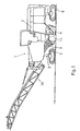
- a road milling machine 1 In Fig. 1, a road milling machine 1 is shown, in which the Fräsrohrschnell hierarchical system described below can be used.
- Road milling machines generally consist of a machine frame 2 on which an internal combustion engine and a control station is mounted.
- the self-propelled road milling machine has height-adjustable, attached to the machine frame 2 lifting columns 3, where support wheels or track assemblies 5 are mounted.
- the milling drum 4 is located under the machine frame 2 in a roller box 11, which is bounded laterally by the side plates 12,13.
- the processed from the milling drum 4 material is dropped in a conventional manner on a first conveyor belt 9 and conveyed to a second, height-adjustable and pivotable conveyor belt 16.
- a milling drum 4 is rotatable between side plates orthogonal to the axis of the milling drum. 12,13 of the roller box 11 and is driven via a mounted on the drive side side plate 12 drive means 6 and a reduction gear 8.
- the milling drum 4 consists of a on a drive-side side plate 12 arranged housing 26 of the reduction gear 8 coupled roller base 14 and a one-piece milling tube 10 which is removably attached to the roller body 14.
- the roll main body 14 is disposed axially adjacent to the reduction gear part 8b.
- the roller base body 14 transmits the torque of the reduction gear 8 to the respective inserted milling tube 10.
- usable milling tubes 10 different milling width and different tooling are available for different roadworks and can be replaced quickly.
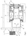
- Fig. 2 shows a first embodiment in which the drive means 6 is arranged on the drive-side side plate 12, of which in Fig. 2, only the pulley 35 is shown.
- the internal combustion engine drives this pulley 35, for example via a compound V-belt.
- the pulley 35 is coupled directly to a coupling point 18 with a first reduction stage of the reduction gear 8 in a drive-side gear part 8a.
- a further reduction stage is coupled to the first reduction stage via a transmission shaft 28.
- the second reduction stage is arranged in a preferably circular-cylindrical housing 26 which is arranged on the milling-side side of the drive-side side plate 12.
- the housing 26 forms the output element of the reduction gear. 8
- a roller base 14 is mounted coaxially to the housing 26 by means of an end face provided on the roller body annular flange 15, wherein the free end of the roller body 14 is mounted in a floating bearing in the drive side side plate 12 opposite side plate 13 ,
- the side plate 13 is arranged on the neutral side of the road milling machine, which indicates the side in which a near-edge milling is possible.
- the annular flange 15 of the roller base body 14 has a maximum of the same outer diameter as the cylindrical housing 26, wherein the inner diameter of the annular flange 15 is seated on a cylindrical spigot 27 of the housing 26, so that ensures a precisely coaxial aligned position of the roller body 14 to the reduction gear 8 is.
- a second annular flange 17 is provided on the roller base 14, which serves as a fastening means for the milling tubes 10.
- annular flanges 19 or other fastening means radially inwardly which cooperate with the annular flange 17.
- the annular flange 17 transmits the torque of the roller base body 14 to the milling tube 10.
- the milling tube 10 is equipped, for example, with chisels 22 whose engagement circle 24 in FIGS. is indicated by the dashed line.
- the maximum milling depth FT is indicated by a further dashed line below the side plates 12, 13.
- the easily removable side plate 13 is preferably pivotable, but may alternatively be axially removable.
- the milling tube shown in Fig. 2 has a milling width of 750 mm.
- the drive side facing free end of the milling tube 10 is supported on a support ring 29 which is slid onto the housing 26 and fixed there. From this radial support ring 29 is a fixed to the support ring 29 protective tube 30 from which coaxially surrounds the circular cylindrical housing 26 and the housing 26 of the reduction gear 8 protects against damage. Between the radial support ring 29 and the milling tube 10, a floating bearing is formed, wherein the milling tube 10 can slide on the support ring 29.
- the radial support ring 29 and the protective tube 30 may be secured to the milling tube 10, wherein the common construction of the support ring 29 and the protective tube 30 seated on the housing 26 and on the seat on the parallel to the transmission shaft 28 extending lateral surface 25 of the housing 26 in the type of a floating bearing can slide.
- the roller main body 14 is in the embodiments of FIGS. 2 to 5 with the housing 26 of the reduction gear 8 and pre-assembled with the annular flange 19. If a change of the milling tube 10 due to another task in the milling required, this change can be performed quickly by first the side plate 13 is dismantled or pivoted. Then the glands between the milling tube and the annular flange 19 must be removed, after which the entire milling tube can be deducted from the null side. Subsequently, the radial support ring 29 is withdrawn with the attached thereto support tube 30 from its seat on the housing 26. They can remain on the housing if the milling tube is only exchanged for reasons of wear and a similar milling tube or another type of milling tube of the same milling width, eg for fine milling, is pushed back.
- the assembly is done in reverse order. First, therefore, the support ring 29 is pushed with the attached protective tube 30 to the seat on the lateral surface 25 of the housing 26 and fixed there. Subsequently, the milling tube 10 can be pushed onto the roller base body 14 and the radial support ring 29.
- the milling tube 10 is screwed to the annular flange 19, wherein at the zero side facing the end of the milling tube 10, a further annular flange 33 may be arranged as a front end cover to the front end of the milling tube 10, an ingress of dirt into the interior of the milling tube 10 prevent.
- the support ring 29 may also be integral with the milling tube 10, in which case the milling tube 10 is pushed together with the support ring 29 on the roller body 14. Also, the annular flange 19 may in principle be integral with the milling tube 10.
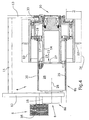
- FIG. 3 largely corresponds to the embodiment of FIG. 2, wherein the milling tube 10 has a maximum milling width between the side plates 12,13.
- the radially supporting annular flange 29 is supported on the drive-side end of the housing 26.
- the attached to the annular flange 29 protective tube 30 is shortened and terminates at the front end of the housing 26, which faces the drive side.
- annular flange 29 are secured to the protective tube 30 to the milling tube 10 and are pushed together with this on the lateral surface 25 of the housing 26.
- the milling tube 10 is even shorter than in the embodiment of FIG. 2, so that a second radial support of the milling tube 10 can be omitted.
- the protective tube 30 is fixed to the annular flange 19 of the milling tube 10.
- the milling tube 10 is pushed together with the protective tube 30 on the seat on the lateral surface 25 of the housing 26.
- FIGS. 2 to 5 when changing the milling width both the reduction gear and the roller main body 14 remain unchanged, while the milling tubes can be mounted or dismounted axially from the neutral side. Access from the drive side is not required.
- FIG. 5 shows a milling tube with a short milling width, which is bolted to the roller base body 14 only via the annular flange 19.
Landscapes
- Engineering & Computer Science (AREA)
- Mechanical Engineering (AREA)
- Mining & Mineral Resources (AREA)
- Architecture (AREA)
- Civil Engineering (AREA)
- Structural Engineering (AREA)
- Road Repair (AREA)
- Milling Processes (AREA)
- Rollers For Roller Conveyors For Transfer (AREA)
- Adjustment And Processing Of Grains (AREA)
- Road Paving Machines (AREA)
- Grinding Of Cylindrical And Plane Surfaces (AREA)
- Control Of Position, Course, Altitude, Or Attitude Of Moving Bodies (AREA)
- Pharmaceuticals Containing Other Organic And Inorganic Compounds (AREA)
- General Details Of Gearings (AREA)
Claims (19)
- Engin automobile de fraisage routier comportant un châssis (2) dans lequel une fraise (4) est montée de façon à pouvoir tourner entre des plaques latérales (12, 13) s'étendant orthogonalement à l'axe de la fraise (4), la fraise (4) qui comporte un corps de base de fraise (14) et un tube de fraisage (10) pouvant être entraînée par un dispositif d'entraînement (6) monté du côté extérieur sur la plaque latérale (12) du côté de l'entraînement et par un engrenage réducteur (8), et la plaque latérale (13), opposée à la plaque latérale (12) du côté de l'entraînement, pouvant être démontée aisément afin de remplacer des tubes de fraisage (10) de différentes largeurs de fraisage qui peuvent être utilisés alternativement, et définissant le côté de référence de l'engin (1) sur lequel la fraise (4) repose sensiblement à fleur avec un côté frontal pour permettre un fraisage près des bords,
caractérisé en ce que
l'engrenage réducteur (8) est placé du côté de l'entrainement,
l'engrenage réducteur (8) comporte un élément de sortie qui est placé du côté intérieur de la plaque latérale (12) du côté de l'entraînement et dont la surface d'enveloppe (25) forme un siège pour des éléments de tube de fraisage coulissant depuis le côté de référence, et
le corps de base de fraise (14) est couplé à l'engrenage réducteur (8) du côté frontal libre (23) de l'élément de sortie sans entraver le coulissement des éléments de tube de fraisage. - Engin automobile de fraisage routier selon la revendication 1, caractérisé en ce que les éléments de tube de fraisage sont constitués des extrémités, du côté de l'entraînement, des tubes de fraisage (10) ou des dispositifs de support radiaux destinés aux tubes de fraisage (10) et/ou des dispositifs de protection tubulaire destinés à l'élément de sortie.
- Engin automobile de fraisage routier selon la revendication 2, caractérisé en ce que les tubes de fraisage (10) et/ou les dispositifs de support radiaux destinés aux tubes de fraisage (10) et/ou les dispositifs de protection tubulaires sont d'une seule pièce.
- Engin automobile de fraisage routier selon les revendications 1 à 3, caractérisé en ce que l'élément de sortie a la forme en coupe transversale d'un cylindre à base circulaire.
- Engin automobile de fraisage routier selon l'une des revendications 1 à 4, caractérisé en ce que l'élément de sortie est constitué d'un boîtier (26) de l'engrenage réducteur (8).
- Engin automobile de fraisage routier selon l'une des revendications 1 à 5, caractérisé en ce que le corps de base de fraise (14) a un diamètre extérieur maximum qui n'est pas supérieur au diamètre extérieur de l'élément de sortie (26).
- Engin automobile de fraisage routier selon l'une des revendications 1 à 6, caractérisé en ce que l'élément de sortie peut recevoir des dispositifs de support et/ou de protection radiaux tubulaires ou annulaires sur au moins une partie de la longueur axiale totale.
- Engin automobile de fraisage de routier selon l'une des revendications 1 à 7, caractérisé en ce que les dispositifs de support radiaux forment sur l'élément de sortie (26) un palier libre destiné au tube de fraisage (10).
- Engin automobile de fraisage routier selon l'une des revendications 1 à 8, caractérisé en ce qu'un dispositif de centrage (27) destiné au corps de base de fraise (14) est placé du côté frontal du boîtier (26).
- Engin automobile de fraisage routier selon l'une des revendications 1 à 9, caractérisé en ce que l'extrémité libre du corps de base de fraise (14) est montée d'un côté dans la plaque latérale (13) aisément démontable qui est opposée à la plaque latérale (12) du côté de entraînement.
- Engin automobile de fraisage routier selon l'une des revendications 1 à 10, caractérisé en ce qu'un tube de protection (30) s'engageant par-dessus l'élément de sortie et servant de dispositif de protection est fixé au dispositif de protection radial (29) destiné au tube de fraisage (10).
- Engin automobile de fraisage routier selon l'une des revendications 5 à 10, caractérisé en ce que le boîtier (26) servant d'élément de sortie a un diamètre extérieur de 400 mm maximum, avantageusement de 350 mm maximum.
- Engin automobile de fraisage routier selon l'une des revendications 1 à 12, caractérisé en ce que le corps de base de fraise (14) comporte une première collerette annulaire (15) du côté frontal qui peut être couplée axialement depuis le côté de référence au côté frontal de l'élément de sortie (26), ainsi qu'une deuxième collerette radiale annulaire (17) qui repose sans pouvoir tourner sur le corps de base de fraise (14) et qui peut être couplée axialement à un dispositif de support (19) s'étendant radialement vers l'intérieur depuis le tube de fraisage (10).
- Engin automobile de fraisage routier selon l'une des revendications 1 à 13, caractérisé en ce qu'une bague de support radial (29) servant de dispositif de support du tube de fraisage (10) est placée à l'extrémité frontale du tube de fraisage (10) et repose coaxialement et avec correspondance de forme sur l'élément de sortie (26).
- Engin automobile de fraisage routier selon l'une des revendications 1 à 14, caractérisé en ce que l'engrenage réducteur (8) comporte au moins un étage de réduction dans une partie d'engrenage (8a) du côté de l'entraînement à l'emplacement de couplage (18) avec le dispositif d'entraînement (6) et au moins un autre étage de réduction dans une partie d'engrenage (8b), du côté de la fraise, qui est entourée par le boîtier (26).
- Engin automobile de fraisage routier selon la revendication 15, caractérisé en ce que l'au moins un étage de réduction du côté de l'entraînement est placé en étant décalé axialement par rapport à au moins un étage de réduction du côté de la fraise.
- Engin automobile de fraisage routier selon l'une des revendications 15 ou 16, caractérisé en ce que l'au moins un étage de réduction du côté de l'entraînement est placé du côté, opposé à la fraise (4), de la plaque latérale (12), du côté de l'entraînement, du châssis (2).
- Engin automobile de fraisage routier selon l'une des revendications 15 à 17, caractérisé en ce que l'au moins un étage de réduction du côté de l'entraînement est couplé par l'intermédiaire d'un arbre d'engrenage (28) à l'au moins un autre étage de réduction.
- Engin automobile de fraisage routier selon l'une des revendications 1 à 18, caractérisé en ce que la plaque latérale (13) aisément démontable est apte à pivoter pour remplacer les tubes de fraisage (10).
Applications Claiming Priority (5)
| Application Number | Priority Date | Filing Date | Title |
|---|---|---|---|
| DE10230784 | 2002-07-09 | ||
| DE10230784 | 2002-07-09 | ||
| DE10232489 | 2002-07-18 | ||
| DE10232489A DE10232489A1 (de) | 2002-07-09 | 2002-07-18 | Selbstfahrende Straßenfräsmaschine |
| PCT/EP2003/004517 WO2004005623A1 (fr) | 2002-07-09 | 2003-04-30 | Fraiseuse de route automotrice |
Publications (2)
| Publication Number | Publication Date |
|---|---|
| EP1520076A1 EP1520076A1 (fr) | 2005-04-06 |
| EP1520076B1 true EP1520076B1 (fr) | 2006-01-18 |
Family
ID=30116618
Family Applications (1)
| Application Number | Title | Priority Date | Filing Date |
|---|---|---|---|
| EP03720545A Expired - Lifetime EP1520076B1 (fr) | 2002-07-09 | 2003-04-30 | Fraiseuse de route automotrice |
Country Status (15)
| Country | Link |
|---|---|
| US (1) | US7144192B2 (fr) |
| EP (1) | EP1520076B1 (fr) |
| JP (1) | JP4190494B2 (fr) |
| KR (1) | KR101005186B1 (fr) |
| CN (1) | CN100365212C (fr) |
| AT (1) | ATE316169T1 (fr) |
| AU (1) | AU2003224140B2 (fr) |
| BR (1) | BR0311553B1 (fr) |
| CA (1) | CA2481779C (fr) |
| DE (1) | DE50302240D1 (fr) |
| ES (1) | ES2255672T3 (fr) |
| HK (1) | HK1076134A1 (fr) |
| MX (1) | MXPA04012008A (fr) |
| RU (1) | RU2308561C2 (fr) |
| WO (1) | WO2004005623A1 (fr) |
Cited By (3)
| Publication number | Priority date | Publication date | Assignee | Title |
|---|---|---|---|---|
| DE102006015506B3 (de) * | 2006-03-31 | 2007-11-08 | Wirtgen Gmbh | Fräswalze für eine Baumaschine, Baumaschine sowie Getriebeeinheit für eine Fräswalze |
| WO2010003436A1 (fr) * | 2008-07-09 | 2010-01-14 | Marini S.P.A. | Fraiseuse routière avec tambour de fraisage remplaçable pour différentes largeurs de coupe |
| DE102009059064A1 (de) * | 2009-12-18 | 2011-06-22 | Wirtgen GmbH, 53578 | Selbstfahrende Straßenfräsmachine |
Families Citing this family (25)
| Publication number | Priority date | Publication date | Assignee | Title |
|---|---|---|---|---|
| DE102006062129B4 (de) | 2006-12-22 | 2010-08-05 | Wirtgen Gmbh | Straßenbaumaschine sowie Verfahren zur Messung der Frästiefe |
| DE102007019202B4 (de) * | 2007-04-20 | 2015-05-21 | Wirtgen Gmbh | Selbstfahrende Baumaschine, inbesondere Straßenfräsmaschine, Recycler oder Stabilisierer |
| DE102009014730B3 (de) * | 2009-03-25 | 2010-10-28 | Wirtgen Gmbh | Auswerfer bzw. Auswerfereinheit für eine Straßenfräsmaschine oder dergleichen |
| US8469456B2 (en) | 2009-03-25 | 2013-06-25 | Wirtgen Gmbh | Ejector unit for a road milling machine or the like |
| US8523290B2 (en) * | 2009-04-10 | 2013-09-03 | Kennametal Inc. | Rotatable cutting tool-tool holder-base assembly |
| US8523289B2 (en) | 2009-04-10 | 2013-09-03 | Kennametal Inc. | Retention assembly for cutting bit |
| US8256847B2 (en) * | 2010-11-30 | 2012-09-04 | Hall David R | Rotational milling chamber |
| DE102011108016A1 (de) * | 2011-07-19 | 2013-01-24 | Liebherr-Components Biberach Gmbh | Selbstfahrender Oberflächenfräser |
| US8714660B2 (en) * | 2012-07-16 | 2014-05-06 | Caterpillar Paving Products Inc. | Chamber for milling machine |
| DE102013208645B4 (de) * | 2013-05-10 | 2018-01-11 | Wirtgen Gmbh | Vorrichtung, insbesondere Kleinfräse, zum Bearbeiten von Straßenoberflächen |
| DE102013013304A1 (de) * | 2013-08-12 | 2015-02-12 | Wirtgen Gmbh | Selbstfahrende Baumaschine zum Bearbeiten von Fahrbahnen oder Bodenoberflächen und Verfahren zum Kühlen der Fräswerkzeuge einer Fräswalze einer selbstfahrenden Baumaschine |
| USD774561S1 (en) * | 2014-01-24 | 2016-12-20 | Bomag Gmbh | Cold milling machine |
| USD774562S1 (en) * | 2014-07-22 | 2016-12-20 | Bomag Gmbh | Cold milling machine |
| USD755859S1 (en) * | 2014-08-12 | 2016-05-10 | Bomag Gmbh | Milling machine |
| CN105178145B (zh) * | 2015-09-07 | 2018-01-12 | 南陵旺科知识产权运营有限公司 | 一种轻便可调压型自行进轧路装置 |
| DE102017208775A1 (de) * | 2017-05-23 | 2018-11-29 | Wirtgen Gmbh | Bodenbearbeitungsmaschine, deren Arbeitsvorrichtung mit einem Bord-Aktuator aus ihrer Betriebsposition verlagerbar ist |
| EP3896224A1 (fr) * | 2017-05-23 | 2021-10-20 | Wirtgen GmbH | Machine de traitement du sol |
| US10787775B2 (en) * | 2017-07-21 | 2020-09-29 | Roadtec, Inc. | Auxiliary drum drive assembly for milling machine |
| EP3655627A4 (fr) * | 2017-07-21 | 2021-04-21 | Roadtec, Inc. | Libération de courroie d'entraînement pour tambour de coupe de fraiseuse et ensemble entraînement de tambour auxiliaire |
| USD866618S1 (en) * | 2018-03-16 | 2019-11-12 | Wirtgen Gmbh | Body panels for a road milling machine |
| CN109112930B (zh) * | 2018-07-25 | 2020-11-20 | 温州澳鼎建材有限公司 | 一种道路施工专用洒水碾压车 |
| KR102259506B1 (ko) | 2019-10-15 | 2021-06-02 | 한국도로공사 | 노면절삭기의 먼지제거장치 |
| DE102020111311B4 (de) * | 2020-04-24 | 2023-07-27 | Wirtgen Gmbh | Wechselaggregat zur texturierenden Bodenoberflächenbearbeitung und Straßenbaumaschine mit einem solchen Wechselaggregat |
| IT202000013528A1 (it) | 2020-06-08 | 2021-12-08 | Seppi M S P A | Macchina con un rotore portautensili cavo cilindrico |
| US11674273B2 (en) | 2021-10-06 | 2023-06-13 | Caterpillar Paving Products Inc. | Milling drum with alignment interface |
Family Cites Families (13)
| Publication number | Priority date | Publication date | Assignee | Title |
|---|---|---|---|---|
| US3072391A (en) * | 1960-06-21 | 1963-01-08 | James F Mcdarrah | Disintegrating machine having cutting and impact action |
| DE3249844C2 (en) * | 1982-04-15 | 1989-03-09 | Alfred Dr. 2095 Obermarschacht De Hackmack | Attachment device for treating road coverings |
| US4614379A (en) * | 1982-09-04 | 1986-09-30 | Reinhard Wirtgen | Apparatus for roughening road surfaces |
| US4704045A (en) | 1985-10-11 | 1987-11-03 | Taylor Thomas M | Apparatus and method for pulverizing asphalt |
| US4720207A (en) * | 1986-08-29 | 1988-01-19 | Koehring Company | Segmented rotor |
| DE4037448B4 (de) * | 1990-11-24 | 2005-09-29 | Wirtgen Gmbh | Fräsvorrichtung für Straßenfräsmaschinen |
| US5395417A (en) * | 1993-01-26 | 1995-03-07 | Double T Equipment Manufacturing Ltd. | Apparatus and process used in working windrowed ingredients to produce pre-wet cycle mushroom compost |
| US5505598A (en) | 1994-07-29 | 1996-04-09 | Wirtgen America, Inc. | Milling machine with multi-width cutter |
| DE19504495A1 (de) * | 1995-02-12 | 1996-08-22 | Wirtgen Gmbh | Maschine zur Erneuerung von Fahrbahnen |
| DE19932396A1 (de) * | 1999-07-14 | 2001-02-01 | Wirtgen Gmbh | Baumaschine sowie Fräswalze |
| US6210071B1 (en) * | 1999-09-27 | 2001-04-03 | Astec Industries, Inc. | Method and apparatus for cutting rumble strips in a roadway |
| KR100402150B1 (ko) | 2000-09-21 | 2003-10-17 | 유옥경 | 유압식 승강시스템을 갖춘 평삭장치 |
| US6547484B2 (en) * | 2001-02-14 | 2003-04-15 | Dustrol, Inc. | Apparatus for cutting rumble strips in a road surface |
-
2003
- 2003-04-30 WO PCT/EP2003/004517 patent/WO2004005623A1/fr active IP Right Grant
- 2003-04-30 JP JP2004518491A patent/JP4190494B2/ja not_active Expired - Fee Related
- 2003-04-30 AU AU2003224140A patent/AU2003224140B2/en not_active Ceased
- 2003-04-30 DE DE50302240T patent/DE50302240D1/de not_active Expired - Lifetime
- 2003-04-30 AT AT03720545T patent/ATE316169T1/de active
- 2003-04-30 BR BRPI0311553-4B1A patent/BR0311553B1/pt not_active IP Right Cessation
- 2003-04-30 ES ES03720545T patent/ES2255672T3/es not_active Expired - Lifetime
- 2003-04-30 KR KR1020047020322A patent/KR101005186B1/ko active IP Right Grant
- 2003-04-30 RU RU2005103231/03A patent/RU2308561C2/ru active
- 2003-04-30 CN CNB038135701A patent/CN100365212C/zh not_active Expired - Fee Related
- 2003-04-30 EP EP03720545A patent/EP1520076B1/fr not_active Expired - Lifetime
- 2003-04-30 US US10/511,031 patent/US7144192B2/en not_active Expired - Lifetime
- 2003-04-30 MX MXPA04012008A patent/MXPA04012008A/es active IP Right Grant
- 2003-04-30 CA CA002481779A patent/CA2481779C/fr not_active Expired - Fee Related
-
2005
- 2005-08-16 HK HK05107063A patent/HK1076134A1/xx not_active IP Right Cessation
Cited By (7)
| Publication number | Priority date | Publication date | Assignee | Title |
|---|---|---|---|---|
| DE102006015506B3 (de) * | 2006-03-31 | 2007-11-08 | Wirtgen Gmbh | Fräswalze für eine Baumaschine, Baumaschine sowie Getriebeeinheit für eine Fräswalze |
| US7901011B2 (en) | 2006-03-31 | 2011-03-08 | Wirtgen Gmbh | Milling drum for a construction machine, construction machine as well as gearbox unit for a milling drum |
| US8118369B2 (en) | 2006-03-31 | 2012-02-21 | Wirtgen Gmbh | Milling drum for a construction machine, construction machine as well as gearbox unit for a milling drum |
| WO2010003436A1 (fr) * | 2008-07-09 | 2010-01-14 | Marini S.P.A. | Fraiseuse routière avec tambour de fraisage remplaçable pour différentes largeurs de coupe |
| US8474919B2 (en) | 2008-07-09 | 2013-07-02 | Marini S.P.A. | Road milling machine with replaceable milling drum with different cutting widths |
| DE102009059064A1 (de) * | 2009-12-18 | 2011-06-22 | Wirtgen GmbH, 53578 | Selbstfahrende Straßenfräsmachine |
| DE102009059064B4 (de) * | 2009-12-18 | 2012-04-26 | Wirtgen Gmbh | Selbstfahrende Straßenfräsmaschine |
Also Published As
| Publication number | Publication date |
|---|---|
| DE50302240D1 (de) | 2006-04-06 |
| ES2255672T3 (es) | 2006-07-01 |
| BR0311553B1 (pt) | 2013-08-13 |
| MXPA04012008A (es) | 2005-03-07 |
| KR101005186B1 (ko) | 2011-01-04 |
| RU2308561C2 (ru) | 2007-10-20 |
| JP2005532488A (ja) | 2005-10-27 |
| US20050158120A1 (en) | 2005-07-21 |
| AU2003224140B2 (en) | 2008-05-08 |
| JP4190494B2 (ja) | 2008-12-03 |
| EP1520076A1 (fr) | 2005-04-06 |
| KR20050024333A (ko) | 2005-03-10 |
| ATE316169T1 (de) | 2006-02-15 |
| CA2481779C (fr) | 2009-07-28 |
| AU2003224140A1 (en) | 2004-01-23 |
| WO2004005623A1 (fr) | 2004-01-15 |
| CA2481779A1 (fr) | 2004-01-15 |
| BR0311553A (pt) | 2005-04-12 |
| RU2005103231A (ru) | 2005-10-27 |
| US7144192B2 (en) | 2006-12-05 |
| CN100365212C (zh) | 2008-01-30 |
| CN1659341A (zh) | 2005-08-24 |
| HK1076134A1 (en) | 2006-01-06 |
Similar Documents
| Publication | Publication Date | Title |
|---|---|---|
| EP1520076B1 (fr) | Fraiseuse de route automotrice | |
| EP1194651B1 (fr) | Engin de construction et cylindre de fraisage | |
| DE102006015506B3 (de) | Fräswalze für eine Baumaschine, Baumaschine sowie Getriebeeinheit für eine Fräswalze | |
| EP2336426B1 (fr) | Machine automobile à fraiser la chaussée | |
| DE2822686C2 (fr) | ||
| EP2255923B1 (fr) | Plateau tournant | |
| EP2492071B1 (fr) | Moteur de fraisage doté de plusieurs broches | |
| DE1481875B2 (de) | Haspel zum ausgleich von lasten | |
| DE3225235C2 (fr) | ||
| EP3775535B1 (fr) | Palier à roulement de grande dimension | |
| EP3872261B1 (fr) | Machine de traitement du sol et structure de support à liaison par complémentarité de forme entre le module de travail rotatif et son coussinet de pivotement | |
| DE102012008252A1 (de) | Fräsereinrichtung für eine Bodenfräsmaschine, Fräswalze für eine solche Fräseinrichtung und Bodenfräsmaschine mit einer solchen Fräseinrichtung | |
| DE69824509T2 (de) | Walzwerk | |
| EP2801666B1 (fr) | Fraiseuse routière, en particulier petite fraiseuse, destinée à traiter les surfaces routières | |
| DE10232489A1 (de) | Selbstfahrende Straßenfräsmaschine | |
| DE2915652A1 (de) | Mechanische treibvorrichtung fuer einen auf einer stationaeren achse gelagerten drehbaren mantel, insbesondere fuer einen mantel einer biegekompensierten walze bei einer papiermaschine | |
| DE19539249A1 (de) | Fräse mit Abstützbuchse | |
| DE2349894B2 (de) | Antrieb mit anflanschbarem motor und kegeltrieb | |
| DE2921977A1 (de) | Wellenantriebselement | |
| DE102004025567A1 (de) | Straßenfräse | |
| EP1619418B1 (fr) | Unité d'entraînement avec bouchon d' adaptation | |
| EP4074898B1 (fr) | Excavatrice à fraises et procédé de changement de la largeur de la fraise | |
| EP0038320B1 (fr) | Cage pour rouleaux entraîneurs dans une installation de coulée | |
| EP1256398B1 (fr) | Laminoir transversal | |
| EP1066890A1 (fr) | Dispositif pour changer l'écrou de serrage d'une bague de laminage |
Legal Events
| Date | Code | Title | Description |
|---|---|---|---|
| PUAI | Public reference made under article 153(3) epc to a published international application that has entered the european phase |
Free format text: ORIGINAL CODE: 0009012 |
|
| 17P | Request for examination filed |
Effective date: 20040721 |
|
| AK | Designated contracting states |
Kind code of ref document: A1 Designated state(s): AT BE BG CH CY CZ DE DK EE ES FI FR GB GR HU IE IT LI LU MC NL PT RO SE SI SK TR |
|
| AX | Request for extension of the european patent |
Extension state: AL LT LV MK |
|
| GRAP | Despatch of communication of intention to grant a patent |
Free format text: ORIGINAL CODE: EPIDOSNIGR1 |
|
| GRAS | Grant fee paid |
Free format text: ORIGINAL CODE: EPIDOSNIGR3 |
|
| DAX | Request for extension of the european patent (deleted) | ||
| GRAA | (expected) grant |
Free format text: ORIGINAL CODE: 0009210 |
|
| REG | Reference to a national code |
Ref country code: HK Ref legal event code: DE Ref document number: 1076134 Country of ref document: HK |
|
| AK | Designated contracting states |
Kind code of ref document: B1 Designated state(s): AT BE BG CH CY CZ DE DK EE ES FI FR GB GR HU IE IT LI LU MC NL PT RO SE SI SK TR |
|
| PG25 | Lapsed in a contracting state [announced via postgrant information from national office to epo] |
Ref country code: IE Free format text: LAPSE BECAUSE OF FAILURE TO SUBMIT A TRANSLATION OF THE DESCRIPTION OR TO PAY THE FEE WITHIN THE PRESCRIBED TIME-LIMIT Effective date: 20060118 Ref country code: FI Free format text: LAPSE BECAUSE OF FAILURE TO SUBMIT A TRANSLATION OF THE DESCRIPTION OR TO PAY THE FEE WITHIN THE PRESCRIBED TIME-LIMIT Effective date: 20060118 Ref country code: SI Free format text: LAPSE BECAUSE OF FAILURE TO SUBMIT A TRANSLATION OF THE DESCRIPTION OR TO PAY THE FEE WITHIN THE PRESCRIBED TIME-LIMIT Effective date: 20060118 Ref country code: SK Free format text: LAPSE BECAUSE OF FAILURE TO SUBMIT A TRANSLATION OF THE DESCRIPTION OR TO PAY THE FEE WITHIN THE PRESCRIBED TIME-LIMIT Effective date: 20060118 Ref country code: RO Free format text: LAPSE BECAUSE OF FAILURE TO SUBMIT A TRANSLATION OF THE DESCRIPTION OR TO PAY THE FEE WITHIN THE PRESCRIBED TIME-LIMIT Effective date: 20060118 |
|
| REG | Reference to a national code |
Ref country code: GB Ref legal event code: FG4D Free format text: NOT ENGLISH |
|
| REG | Reference to a national code |
Ref country code: CH Ref legal event code: NV Representative=s name: ISLER & PEDRAZZINI AG Ref country code: CH Ref legal event code: EP |
|
| GBT | Gb: translation of ep patent filed (gb section 77(6)(a)/1977) |
Effective date: 20060118 |
|
| REG | Reference to a national code |
Ref country code: IE Ref legal event code: FG4D Free format text: LANGUAGE OF EP DOCUMENT: GERMAN |
|
| REF | Corresponds to: |
Ref document number: 50302240 Country of ref document: DE Date of ref document: 20060406 Kind code of ref document: P |
|
| PG25 | Lapsed in a contracting state [announced via postgrant information from national office to epo] |
Ref country code: SE Free format text: LAPSE BECAUSE OF FAILURE TO SUBMIT A TRANSLATION OF THE DESCRIPTION OR TO PAY THE FEE WITHIN THE PRESCRIBED TIME-LIMIT Effective date: 20060418 Ref country code: DK Free format text: LAPSE BECAUSE OF FAILURE TO SUBMIT A TRANSLATION OF THE DESCRIPTION OR TO PAY THE FEE WITHIN THE PRESCRIBED TIME-LIMIT Effective date: 20060418 Ref country code: BG Free format text: LAPSE BECAUSE OF FAILURE TO SUBMIT A TRANSLATION OF THE DESCRIPTION OR TO PAY THE FEE WITHIN THE PRESCRIBED TIME-LIMIT Effective date: 20060418 |
|
| PG25 | Lapsed in a contracting state [announced via postgrant information from national office to epo] |
Ref country code: MC Free format text: LAPSE BECAUSE OF NON-PAYMENT OF DUE FEES Effective date: 20060430 |
|
| REG | Reference to a national code |
Ref country code: HK Ref legal event code: GR Ref document number: 1076134 Country of ref document: HK |
|
| PG25 | Lapsed in a contracting state [announced via postgrant information from national office to epo] |
Ref country code: PT Free format text: LAPSE BECAUSE OF FAILURE TO SUBMIT A TRANSLATION OF THE DESCRIPTION OR TO PAY THE FEE WITHIN THE PRESCRIBED TIME-LIMIT Effective date: 20060619 |
|
| REG | Reference to a national code |
Ref country code: ES Ref legal event code: FG2A Ref document number: 2255672 Country of ref document: ES Kind code of ref document: T3 |
|
| REG | Reference to a national code |
Ref country code: IE Ref legal event code: FD4D |
|
| ET | Fr: translation filed | ||
| PLBE | No opposition filed within time limit |
Free format text: ORIGINAL CODE: 0009261 |
|
| STAA | Information on the status of an ep patent application or granted ep patent |
Free format text: STATUS: NO OPPOSITION FILED WITHIN TIME LIMIT |
|
| 26N | No opposition filed |
Effective date: 20061019 |
|
| REG | Reference to a national code |
Ref country code: CH Ref legal event code: PCAR Free format text: ISLER & PEDRAZZINI AG;POSTFACH 1772;8027 ZUERICH (CH) |
|
| PG25 | Lapsed in a contracting state [announced via postgrant information from national office to epo] |
Ref country code: CZ Free format text: LAPSE BECAUSE OF FAILURE TO SUBMIT A TRANSLATION OF THE DESCRIPTION OR TO PAY THE FEE WITHIN THE PRESCRIBED TIME-LIMIT Effective date: 20060118 Ref country code: GR Free format text: LAPSE BECAUSE OF FAILURE TO SUBMIT A TRANSLATION OF THE DESCRIPTION OR TO PAY THE FEE WITHIN THE PRESCRIBED TIME-LIMIT Effective date: 20060419 |
|
| PG25 | Lapsed in a contracting state [announced via postgrant information from national office to epo] |
Ref country code: EE Free format text: LAPSE BECAUSE OF FAILURE TO SUBMIT A TRANSLATION OF THE DESCRIPTION OR TO PAY THE FEE WITHIN THE PRESCRIBED TIME-LIMIT Effective date: 20060118 |
|
| PG25 | Lapsed in a contracting state [announced via postgrant information from national office to epo] |
Ref country code: HU Free format text: LAPSE BECAUSE OF FAILURE TO SUBMIT A TRANSLATION OF THE DESCRIPTION OR TO PAY THE FEE WITHIN THE PRESCRIBED TIME-LIMIT Effective date: 20060719 Ref country code: TR Free format text: LAPSE BECAUSE OF FAILURE TO SUBMIT A TRANSLATION OF THE DESCRIPTION OR TO PAY THE FEE WITHIN THE PRESCRIBED TIME-LIMIT Effective date: 20060118 Ref country code: LU Free format text: LAPSE BECAUSE OF NON-PAYMENT OF DUE FEES Effective date: 20060430 |
|
| PG25 | Lapsed in a contracting state [announced via postgrant information from national office to epo] |
Ref country code: CY Free format text: LAPSE BECAUSE OF FAILURE TO SUBMIT A TRANSLATION OF THE DESCRIPTION OR TO PAY THE FEE WITHIN THE PRESCRIBED TIME-LIMIT Effective date: 20060118 |
|
| REG | Reference to a national code |
Ref country code: FR Ref legal event code: PLFP Year of fee payment: 13 |
|
| REG | Reference to a national code |
Ref country code: FR Ref legal event code: PLFP Year of fee payment: 14 |
|
| REG | Reference to a national code |
Ref country code: FR Ref legal event code: PLFP Year of fee payment: 15 |
|
| REG | Reference to a national code |
Ref country code: FR Ref legal event code: PLFP Year of fee payment: 16 |
|
| PGFP | Annual fee paid to national office [announced via postgrant information from national office to epo] |
Ref country code: FR Payment date: 20200421 Year of fee payment: 18 Ref country code: CH Payment date: 20200423 Year of fee payment: 18 Ref country code: NL Payment date: 20200420 Year of fee payment: 18 Ref country code: ES Payment date: 20200516 Year of fee payment: 18 |
|
| PGFP | Annual fee paid to national office [announced via postgrant information from national office to epo] |
Ref country code: GB Payment date: 20200423 Year of fee payment: 18 Ref country code: BE Payment date: 20200420 Year of fee payment: 18 |
|
| PGFP | Annual fee paid to national office [announced via postgrant information from national office to epo] |
Ref country code: AT Payment date: 20200421 Year of fee payment: 18 |
|
| REG | Reference to a national code |
Ref country code: NL Ref legal event code: MM Effective date: 20210501 |
|
| REG | Reference to a national code |
Ref country code: AT Ref legal event code: MM01 Ref document number: 316169 Country of ref document: AT Kind code of ref document: T Effective date: 20210430 |
|
| GBPC | Gb: european patent ceased through non-payment of renewal fee |
Effective date: 20210430 |
|
| REG | Reference to a national code |
Ref country code: BE Ref legal event code: MM Effective date: 20210430 |
|
| PG25 | Lapsed in a contracting state [announced via postgrant information from national office to epo] |
Ref country code: CH Free format text: LAPSE BECAUSE OF NON-PAYMENT OF DUE FEES Effective date: 20210430 Ref country code: AT Free format text: LAPSE BECAUSE OF NON-PAYMENT OF DUE FEES Effective date: 20210430 Ref country code: LI Free format text: LAPSE BECAUSE OF NON-PAYMENT OF DUE FEES Effective date: 20210430 Ref country code: GB Free format text: LAPSE BECAUSE OF NON-PAYMENT OF DUE FEES Effective date: 20210430 Ref country code: FR Free format text: LAPSE BECAUSE OF NON-PAYMENT OF DUE FEES Effective date: 20210430 |
|
| PG25 | Lapsed in a contracting state [announced via postgrant information from national office to epo] |
Ref country code: NL Free format text: LAPSE BECAUSE OF NON-PAYMENT OF DUE FEES Effective date: 20210501 |
|
| REG | Reference to a national code |
Ref country code: ES Ref legal event code: FD2A Effective date: 20220705 |
|
| PG25 | Lapsed in a contracting state [announced via postgrant information from national office to epo] |
Ref country code: ES Free format text: LAPSE BECAUSE OF NON-PAYMENT OF DUE FEES Effective date: 20210501 Ref country code: BE Free format text: LAPSE BECAUSE OF NON-PAYMENT OF DUE FEES Effective date: 20210430 |
|
| PGFP | Annual fee paid to national office [announced via postgrant information from national office to epo] |
Ref country code: IT Payment date: 20220429 Year of fee payment: 20 Ref country code: DE Payment date: 20220419 Year of fee payment: 20 |
|
| REG | Reference to a national code |
Ref country code: DE Ref legal event code: R071 Ref document number: 50302240 Country of ref document: DE |
|
| P01 | Opt-out of the competence of the unified patent court (upc) registered |
Effective date: 20230525 |